How Do I add Voice controls and SWC buttons to the V?
Thanks to Reed with help from Miscreant
Click the images to make them larger
Difficulty: HARD
Items Required:
Weller Soldering Iron (or other device to cut plastic)
Steering wheel control module from GM (Part number 25767333 ~$49 from GMPD.com)
Wire Crimpers
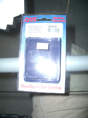
QVS MPC standard connector (see image below- found at local electronics/computer store- NOT radioshack)
Mini Wire Connectors (for 26 guage wire)
Miniature Screwdriver
Crimp connectors (quick disconnect ones are optional)
Bravery
This proceedure will allow you to add the SWC buttons and the voice controls to the V that Cadillac removed to place the DIC buttons.
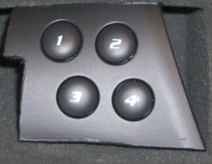
NOTE: As of now you CANNOT reprogram the SWC buttons but they are useful (1- next track, 2- Previous track, 3- Temp up, 4- temp down).
Mounting shown is temporary just to see if I really want this, you can mount them however, whereever you want. This is not difficult to install, but the prewiring does take some time. NO wire cutting is necessary! (yah!)
1. Purchase the V controls from GMPD. It will come as a single piece (in the shape of the V- sorry no picure). When you receive this part, you will need to cut the extra plastic away. I cut it so that the modules are ht eonly thing left as close to the circuit board as possible. I recommend that you remove the circuit boards from the module before you cut in case you slip. Use the weller soldering gun and the correct "knife" tip to cut through the plastic. You should have the following:
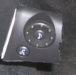
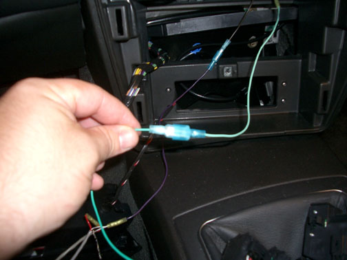
2. Next take the MPC connectors out of the box. You will need 3 total connectors. 1 you will use as is (surprisingly it fits directly into the rear of the SWC buttons module). The other 2 MPC connectors you will modify to fit into the rear of the Voice module because I cannot find the correct connector that is 7 pins.
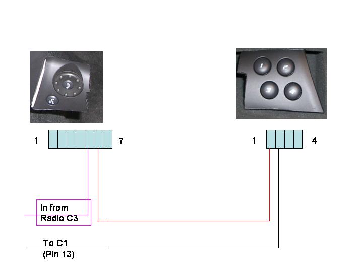
3. Remove the wires from each connector (carefully) using a very small flat screw driver. You are going to reuse the connectors AND the clips you just need to re order them. This will keep you from having to splice into each wire which I think is much cleaner. Rewire the connectors and the new harness as shown in the followind diagram using the splice connectors and placing the wires to the correct terminals (make sure that you are wiring the correct pin- they are marked on the back of the module). Because the Voice module has 7 pins you need to use pliers or the soldering gun to "remove" a terminal from that connector. So, basically you are going to use a single 4 ping connector and a modified 3 pin connector to make the 7 pins. When you place the 3 pin and 4 pin connector next to each other they will fit into the connector fine. However you may need to "adjust" by cutting the top and bottom of the connector where there are "guides" and the locking mechanism (this will not affect its ability to stay in the connector).
The other unused pins in the connector are for backlight and I have not yet gotten that working so you can ignore them.
4. Once your have the wireing harness made up. I placed a quick disconnect on the two ends of the connectors that go to the radio so that I can remove this system easily (without removing the radio). So, wire quick disconnectes on the end of those two wires.
5. Next you will need to aquire the connectors that go into the C1 and C3 connector. I did this by moding some female connectors that I had around the house. I tried two different dealers and they actually let me look through their connectors, but they were not labeled the same as the docuementation that miscreant supplied and therefore i was shooting in the dark. The reverese volskwagen connector did not work in the C3 Connector as it did in Miscreant's nav install. So, I usd wire ends that had female connectors on it and would fit snug and make the necessary low voltage connection.
5. Remove the dashbboard and radio as described here Radio Bezel Remove Proceedure
6. Disconnect the connectors on the back of the radio. Locate pin 13 on Radio connector C1 and Pin 2 on radio Connector C3. See this page for complete diagrams: Connectors in HTML
7. I reconnected the radio connectors and then placed the small strands of wire with quick disconnects (that match up to the wiring harness I made in step 3) in the back of the proper pins. So, The CTS-V DOES NOT HAVE PINS in the locations that you are using. The wires were left out on the V version. The best way to assure they are tight is the connect the connectors and then place the connectors in the back and make sure they are snug.
8. Once connected, I dropped the short wires with quick disconnects behind the radio and re attached the radio in its place. I now had the two wire leads I needed from the radio below it and I could test the connections.
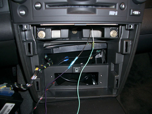
9. At this point I connected my harness and to the quick disconnects to test the connection and make sure that the radio responded (which assures that everything is wired properly)
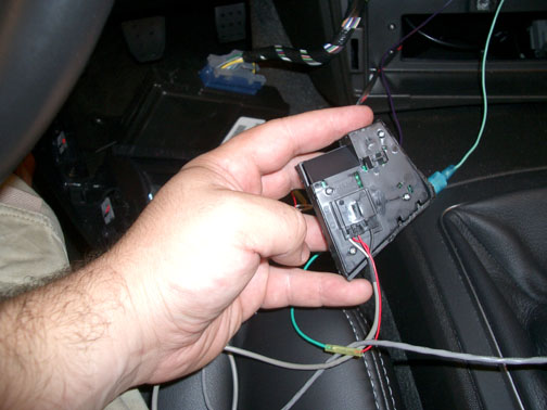
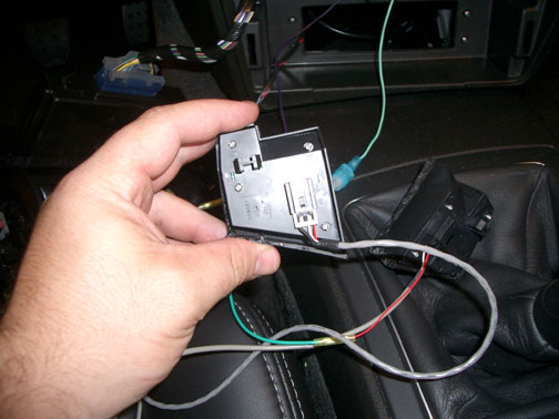
10. I chose to put the SWC controls in the ash tray and the voice module outside to the right of the console (temporarily). See the images below:
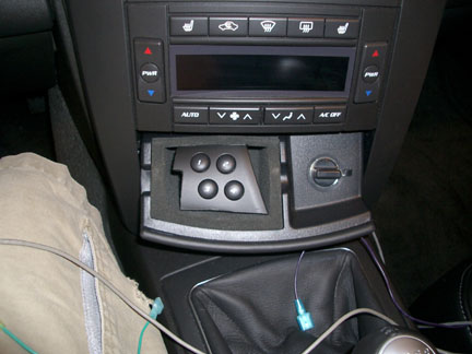
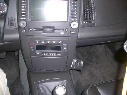
11. Put everything back together and enjoy. If you have any questions please e-mail me and I will try to explain. I am not the best at writing these so please let me know if you have any questions.
|