|
This information is provided as guidance Only. Use this information at your own risk! This site is not affiliated with General Motors or Cadillac. All trademarks are property of their respective owners. |
 |
|
This information is provided as guidance Only. Use this information at your own risk! This site is not affiliated with General Motors or Cadillac. All trademarks are property of their respective owners. |
|
Installing Factory Style XM in the CTSThanks to OdysseusOverview If you have a 2004 or later CTS and want to add XM as if it was factory, you can purchase a kit from www.radiosandmore.com Specify that you have a CTS and they will provide you the cabling. this will work with all CTS radios, but MAY require you to go to the dealer to get the XM band enabled. If that is the case, print the instructions linked below and bring them to the dealer. The dealer MAY charge you for this. Programming instructions (PDF) Serius is not yet available. Here is how to do it yourselfExplanation: Many have fretted over not having XM installed at the factory, since it cannot be retrofitted later. Up until very recently, the only other options were ‘add-on’ plug and play boxes that mounted to the dash, junking up the looks. There is now a solution for adapting the inexpensive XM Direct tuner to the factory head unit, allowing it to look and work like the Cadillac intended. All metadata (song title, artist, etc) will display on the head unit (radio), as will XM specific presets. Disclaimer: Mod at your own risk - double check the schematics when you install the terminals. It’s also a good idea to check continuity of each wire after the terminals are crimped prior to installing them into connectors. I will not accept responsibility for errors or omissions, or incorrectly installed wiring. Preliminary: Since the base (single CD) head unit does not have XM software built in (you need a ‘Band’ button, this mod works for the Bose and Nav. Since the only difference in the various XM GM100 radio package is the harnessing, we simply need to connect the wires to the appropriate terminals in the CTS. First, we need to acquire a XM package that includes the XM Direct tuner with antenna and cables, the GM100 Class-2 serial bus adapter, and harnessing. The easy way is to go to call Radios and More (877-888-2225) www.xmforcadillacs.com and order the RVRCTS/SRX kit. If you have the Nav, or plan to add one, make sure you specifically ask for it, as the regular harness does not include the audible directions and voice command pass-through wires. The cost is $299, shipped free. They will add the four extra wires for the Nav, upon request, but are contemplating a price increase for doing that. If you choose that route, you can stop reading here and jump to ‘final installation’, since the bulk of this write-up shows how to retrofit a cheaper XM package. Be aware that fitting the stiff new harness and its large plastic connectors behind the Nav is a chore, but it can be done. Make sure you write down the radio ID number located on a label on the XM Direct tuner. You can also get this by tuning to channel 1, after the install is complete. Schematics for the CTS radio harnesses are at http://www.cadillacfaq.com/faq/answers/pdf/nav.pdf . Now for the do-it-yourself way to save $100.Radios and More basically buys the standard GM XMD100 kit and makes their own wire harness to adapt it to the CTS. It is a plug and play kit, and well made. But, if you’re a hacker, you can make a harness yourself for under $5, and pocket about $100. Basically, this involves buying a cheaper version of the XM adapter for GM vehicles and adapting it to work with the CTS. Acquire a regular (cheaper) GM XM bundle (XMDGM100) from EBay (~$175, BIN) or MyRadioStore ($199). When you get the package (shown below), it will come with a wire harness adapter to connect a different factory GM radio (but not the CTS) and the factory harness, to get signals to and from the XM adapter. It does have most of the parts we need to retrofit to the CTS, though. The first step is to remove the harness with the white 8 pin connector, which goes to the XM adapter (connector to the right of the picture below), from the spaghetti mess of harnessing that comes with the package. We don’t need the rest of the harness, since we want it to look factory and we’re installing the wires directly into the factory connector, without adapters. 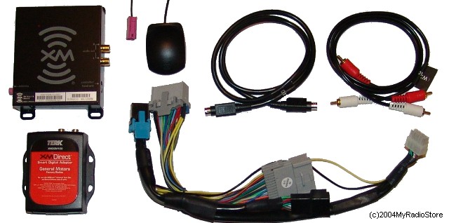 Building the new XM HarnessThe easy way is to simply trace the wires from the white 10 pin connector (on the right) to the unneeded connectors and cut them at that end. You’ll be left with an ~18” harness with the 10 pin white connector on one end (only 6 wires will be installed). You’ll need to install new terminals for it to fit the CTS, but they’re the same terminals we needed for the VSS wire in the Nav Phase-1 install. A reverse VW harness can also be used to pilfer terminals. These are:
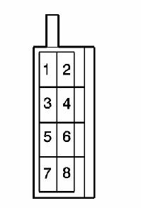
If you don’t want to cut up your new harness, but would rather build your own, it’s very easy. The connector we need is a standard Molex 10 pin Mini-Fit Jr. connector. We’ll also need six wires and terminals. Either use 2’ to 3’ of leftover Belden twisted shielded pair wire from the Phase-2 Nav install, or improvise. Basically we need to crimp six Mini-Fit Jr. Terminals to the ends of each of the six wires. Plug them into the connector filling the top row and the lower right pin location on the bottom row, as viewed from the front of the connector end (see the XMDGM100 pinouts below). Now for the pin-outs of the connectors, so you will know where to plug your wires with their newly crimped terminals into the factory harness. Here is the pin-out of the white connector that goes into the GM100 Class-2 interface box (with the orange label in the first picture). NOTE: All pin-outs for connectors are viewed from the connector end. Terminals will actually install from the back of the connectors. Pin 1 is the upper row left, pin 5 is upper row, right. Pin 6 is lower row left, pin 10 is lower row, right. XMDGM100 (10 pin Mini-Fit Junior)6  10 10
Crimp (or solder the ones from the reverse VW harness) the terminals that you got for C3 onto the other the three audio (pins 4, 5, 10) wires. We’re going to have to splice into existing wire to get to the power/ground and class-2 wires. If you’re daring, you can cut and butt splice or solder these wires into your factory harness for a true factory look. Make sure you shrink wrap all solder or butt crimps. Installing your new XM HarnessBelow is a picture of the back of a Nav with the locations of each of the connectors labeled. The C1, C2, and C3 connectors will be identical in the Base and the Bose systems, but those radios will obviously be missing the RGB video input connector (C4) and the GPS connector. 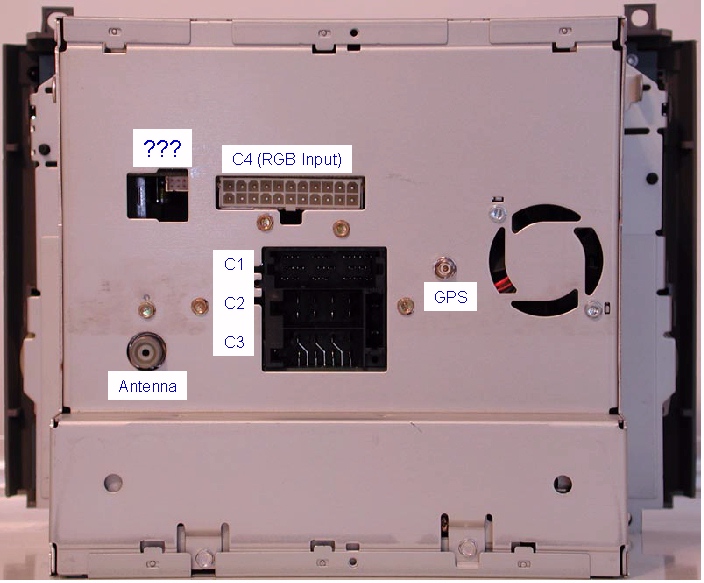
Insert the audio wires (XM connector pins 10, 4, 5) into the C3 connector (pins 1, 3, 4) that goes into the back of the radio, located under C1. C2 and C3 look similar, but note the key on C3. Note that there are three wires already connected in C3 in positions 2, 7, and 8. We need to splice two wires (XM connector pins (1, 3) onto the power and ground (7, 8) wires, since those are already installed in the Nav C3 connector. The pin-out of the C3 connector is shown below. When you’re done, all but pin 5 (and possibly pin 6) should have a wire in C3.
Next, we splice the Class-2 wire from the new harness (XM connector pin 2), into the Yellow, Green, and Blue C1 connector that goes into the back of the radio. This will splice onto the wire which is in pin 11 on C1. 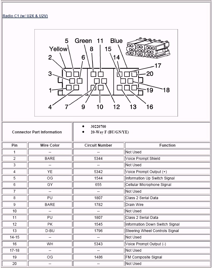
Final Installation:Double check all connections and run the new XM harness from behind where the radio mounts, out to the passenger side, and drop it back in from the bottom, connect it to the XMD100 box. Basically, we don’t want excess cabling directly behind the head unit, or it won’t fit back into place. Connect the 8 pin DIN cable and the red and white RCA cables to the XMD100. Slide the XMD100 so that the white 10 pin connector slides to the right in the slot below the Nav, and the three other cables are exiting the left. This is a tight fit, but will hold the XMD100 in place. Make sure the two audio (red and white RCA’s) and the DIN 8 cable exit the left side of the slot and reappear from below. The concept is to get all wiring out from directly behind the Nav, as it’s a very tight fit, but leave room for connecting the XM Direct tuner, which will install below the ashtray. Now that the harnesses are connected just like the factory ones, we’re ready to actually install the XM tuner and Class-2 adapter. The next step is to mount the antenna. While this sounds very easy, running the single wire to look factory will take several hours. You’ll basically do the same steps in the Nav Phase-2 install for removing the back seat and the trunk liners, so we can zip-tie the wires onto the factory harness. Remove the rear seat bottom (pull straight up on the front, then pull forward to remove). Then four nuts on the bottom of the rear seat back which are now exposed, then four nuts from the trunk holding the top of the seat back. The seat back then can be pulled toward the front of the car. As explained in Phase-2, have a friend help to pull it from under the seat belts, especially the middle one, and remove it, so you don’t scratch the door jams. From the trunk, unscrew the spare tire hold-down so the cover can be lifted (no need to remove it entirely). Unscrew the large (2”) buttons holding the trunk covers in place. First the one between the tail lights comes out, then remove the driver’s side panel, since this is where we’ll run the wiring. Make sure to cover the antenna bottom with double sided tape, so it does not scratch the clear coat every time it gets bumped, you close the trunk, you wash the car, etc. The antenna has about 6’ of tubing covering the antenna wire. I placed the antenna on the trunk, in the center, so the tubing ends at the forward edge of the trunk and drops into the trunk area there. With the trunk open, pill the lower leftmost plastic push-pin and tuck the wire under the trunk liner so it exits to the left of the push-pin. You can reinsert the push-pin. Remove the black electrical tape covering the corrugated wire wrap going from the trunk lid down into the left side of the trunk. Run the antenna wire inside of that, and re-wrap with black electrical tape. 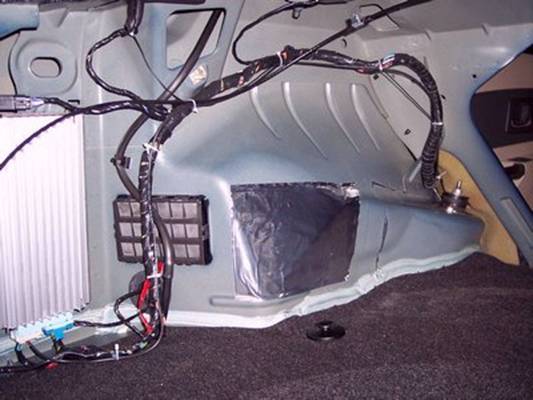
Zip tie the wiring along the factory harness, and have it exit the trunk next to the shock, into the back seat area. Tuck it under the door molding up to the front kick panel having it exit at the top of that. The panel under the steering wheel is held with three Phillips head screws. Remove those screws, allowing the panel to drop a few inches. Tuck the harnessing up and push the ends into the sides of the center stack near the ash tray. Reinstall the three Phillips head screws holding the panel in place. You can reinstall the trunk liner and rear seat at this point. Plug the purple antenna wire, the DIN 8 wire, and the red and white audio cables into the XM Direct tuner and mount it above the transmission hump, just below where the ashtray slides into. It will take some maneuvering to get it to slide in place, but it needs to fit below where the ashtray will mount, so everything fits snug. Put the C1, C2, C3 and FM antenna and GPS antenna connectors back into the radio head unit and slide it back into place, making sure no wires get pinched behind it and keep it from fitting flush. Fasten it with the four screws from when you removed it. Snap the ashtray back in place. You won’t need to reinstall the center bolt, since the clips are more than adequate to hold it in place, and make it easier to remove, if you ever need to in the future. Snap the upper AC vents back in place and you’re done. The moment of truth:Turn on the key and the radio and hit the “Band” button until “XM” comes up. If it doesn’t, you’ll have to have the dealer turn that on that feature with a Tech-2 programmer. The short instructions come in the box with the XMD100. Tune to the preview channel and write down your radio ID number, if you didn’t copy it from the label on the XM Direct tuner before the install. You should hear the XM ads talking through your speakers. Call XM and activate your radio. You’ll need to keep the car parked out doors for a few hours while the codes download. Your done! Is it worth all the effort to save $100? Well, since you’ll have to do the complete install (except crimping on a few terminals) yourself no matter what, or else pay the dealer a few hundred dollars to do it for you. I would say, if you can install the XM box by yourself, and feel comfortable soldering or crimping wire terminals, it’s worth the extra effort to buy terminals and crimp them to save $100. Plus it looks much more factory than the harness that comes with the unit! Thanks Odysseus | ||||||||||||||||||||||||||||||||||||||||||||||||||||||||||||||||||||||||||||||||||||||||||||||||||